
|
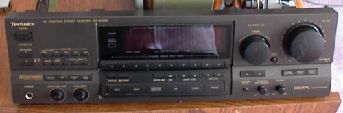
Technics SA-GX505 Receiver to Preamp Conversion |
A couple of months ago my Technics SA-GX505 receiver's output section fizzled. I was watching TV, and I heard the right speaker buzz for a few seconds as the cooling fan spun to top speed, and then the protection relay kicked in. I was able to cycle the power and it would work for a minute or so, and then fizzle again. Dang!
So being the tinkerer I am, I disconnected the unit and brought it over to my desk. Popped the lid open and looked inside. Hmmm... I see circuit board heat discolouration in the power supply regulator sections. I powerd it up with the lid off, and waited for it to fizzle again. When it did, the large heatsink became hot very quickly until it went into protection mode.
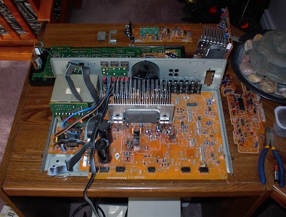
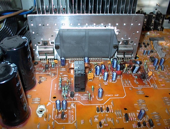
The main heatsink in the receiver has four power transistors used in the voltage regulator sections, and a large amplifier module, marked SVI 3206. I suspect that the module has some problems. Perhaps it is going into oscillation and overheating, or otherwise shorting out somehow. I have read reviews that this receiver is known for overheating. Perhaps the thermal stress has caused problems in the SVI 3206 module. Anyway, for all intensive purposes, the output stage is fried.
Everything else functions fine though...and remote control is very convenient. The SA-GX505 is a very nice unit with parametric EQ and a functional frequency analyzer display on the front. It has basic video switching function too, although I don't use composite video anymore.
Here's my plan of attack: Rip out the SVI 3206 module. Find the signal pins on the circuit board and wire them to connectors on the back panel. Build a new power amp (see my GainClone project), and make that my new system.
The power transformer in the SA-GX505 is nice and hefty. Unfortunately its secondary voltage rating is too high for my GainClone. I'll leave it in the receiver for now.
...Three years later... :)
Sorry for waiting so long to update this page. I saw some renewed interest from a member on the DIY Audio forum and another gentleman who e-mailed me. I did complete the Technics receiver project some time ago. My post about this project is at http://www.diyaudio.com/forums/showthread.php?s=&threadid=17771
Here is my handiwork...
I found this pinout diagram of the SVI module, linked from a forum post at DIYaudio.com.
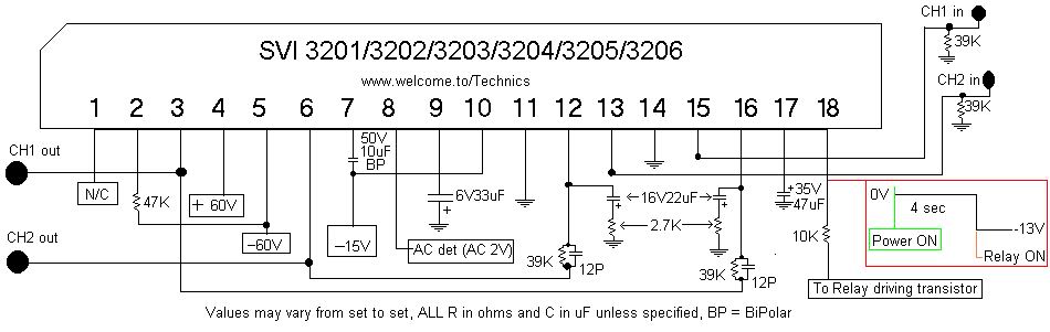
Pins 13 and 15 are the inputs for the SVI 3206 module. I removed the module, and soldered my signal wires to the holes where pins 13 and 15 go.
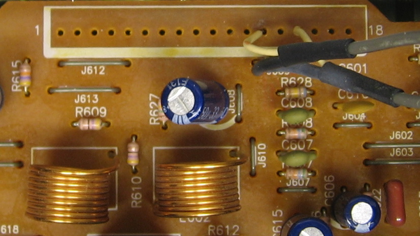
Jumper J609 is connected to signal ground, so I soldered both of my signal ground leads to it.
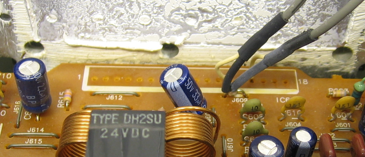
The other ends of the wires lead to a pair of RCA jacks. Right now they hang out the back of the receiver. I haven't got around to properly mounting them in the back of the receiver yet. If you're wondering about the nice heat-shrink job on the wires, I didn't do it. Those wires came out of a junked VCR. :)